555 Timer Schematic : Bouncless Switch with NE555 - Electronic Circuit / Its not listed anymore, but i can still link it in.. Oct 13, 2018 · the 555 timer ic is an integrated circuit used in a variety of timer, pulse generation and oscillator applications. Ic 555 timer ic is one of the most popular integrated circuit chip used for a variety of applications such as astable, monostable, bistable multivibrators, timer circuits, oscillators, pwm (pulse width modulation), ppm (pulse position modulation), square wave generator or pulse generator, etc. Astable mode, monostable mode and bistable mode are the three modes of operation of ic 555. We can use the 555 as a timer for up to 10 minutes. In more simple words, 555 timer is a monolithic timing circuit, which can produce accurate timing pulses with 50% or 100% duty cycle.
I have used two 555 timer ics in this project and both these 555 ics act as astable multivibrators. The 555 timer can be obtained very cheaply from pretty much any electronic retailer. Simple ne555 ic tester circuit diagram. We can use the 555 as a timer for up to 10 minutes. 4th pin is connected to vcc to avoid sudden resets.
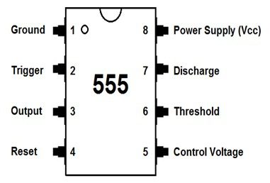
Speed Controller Using 555 from www.electronicshub.org Apr 15, 2020 · people know it as the 555 timer ic. 4th pin is connected to vcc to avoid sudden resets. Ic 555 timer ic is one of the most popular integrated circuit chip used for a variety of applications such as astable, monostable, bistable multivibrators, timer circuits, oscillators, pwm (pulse width modulation), ppm (pulse position modulation), square wave generator or pulse generator, etc. This circuit is also called a delay. Astable mode, monostable mode and bistable mode are the three modes of operation of ic 555. If you want to know all the pinout of the 555 timer, what each pin is and what each pin does, see 555 timer pinout. 555 timer helpers schematic adding of a resistor and capacitor to the trigger will not work for very short trigger or output pulses because there is a rc delay in the decay and recovery of the voltage at the trigger. The first comparator has threshold input to pin 6 and control inputs for pin 5.
I have used two 555 timer ics in this project and both these 555 ics act as astable multivibrators.
If you want to know all the pinout of the 555 timer, what each pin is and what each pin does, see 555 timer pinout. Its not listed anymore, but i can still link it in. Apr 15, 2020 · people know it as the 555 timer ic. It produces pulses whose width can be varied. Dec 07, 2018 · 555 timer ic. 555 timer helpers schematic adding of a resistor and capacitor to the trigger will not work for very short trigger or output pulses because there is a rc delay in the decay and recovery of the voltage at the trigger. Jun 10, 2021 · there is a 555 timer application on this site to achieve the timings you need. I have used two 555 timer ics in this project and both these 555 ics act as astable multivibrators. It was commercialized in 1972 by signetics. The 555 timer can be obtained very cheaply from pretty much any electronic retailer. In 2017, it was said over a billion 555 timers are pr. 2nd and 6th pins are shorted to allow triggering after every cycle. Learn by doing is the best.
In more simple words, 555 timer is a monolithic timing circuit, which can produce accurate timing pulses with 50% or 100% duty cycle. 2nd and 6th pins are shorted to allow triggering after every cycle. Its not listed anymore, but i can still link it in. In the time delay mode of operation, the time is precisely controlled by one external resistor and capacitor. Ic 555 timer ic is one of the most popular integrated circuit chip used for a variety of applications such as astable, monostable, bistable multivibrators, timer circuits, oscillators, pwm (pulse width modulation), ppm (pulse position modulation), square wave generator or pulse generator, etc.
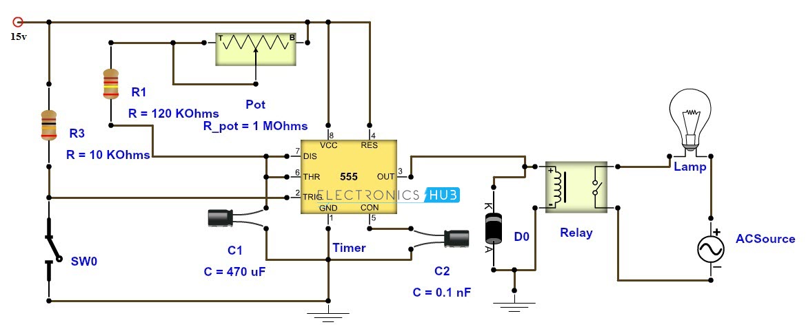
Adjustable Timer Circuit Diagram with Relay Output from www.electronicshub.org We can use the 555 as a timer for up to 10 minutes. In other words, 555 timer is a circuit which may be connected as a stable or monostable multivibrator. Derivatives provide two (556) or four (558) timing circuits in one package. Astable mode, monostable mode and bistable mode are the three modes of operation of ic 555. In more simple words, 555 timer is a monolithic timing circuit, which can produce accurate timing pulses with 50% or 100% duty cycle. Just check the pinouts of the pot. Learn by doing is the best. Dec 07, 2018 · 555 timer ic.
In the time delay mode of operation, the time is precisely controlled by one external resistor and capacitor.
4th pin is connected to vcc to avoid sudden resets. In 2017, it was said over a billion 555 timers are pr. Learn by doing is the best. The 555 timer ic is an integrated circuit (chip) used in a variety of timer, delay, pulse generation, and oscillator applications. It was commercialized in 1972 by signetics. This circuit is also called a delay. It produces pulses whose width can be varied. In the time delay mode of operation, the time is precisely controlled by one external resistor and capacitor. Astable mode, monostable mode and bistable mode are the three modes of operation of ic 555. We can use the 555 as a timer for up to 10 minutes. For a stable operation as an oscillator , the Nov 03, 2018 · 555 timer here, 555 timer runs in free running mode i.e. In other words, 555 timer is a circuit which may be connected as a stable or monostable multivibrator.
2nd and 6th pins are shorted to allow triggering after every cycle. It produces pulses whose width can be varied. Learn by doing is the best. In other words, 555 timer is a circuit which may be connected as a stable or monostable multivibrator. In more simple words, 555 timer is a monolithic timing circuit, which can produce accurate timing pulses with 50% or 100% duty cycle.
How does NE555 timer circuit works | Datasheet | Pinout ... from www.eleccircuit.com Simple ne555 ic tester circuit diagram. Derivatives provide two (556) or four (558) timing circuits in one package. We can use the 555 as a timer for up to 10 minutes. If you want to know all the pinout of the 555 timer, what each pin is and what each pin does, see 555 timer pinout. 555 timer is a digital monolithic integrated circuit (ic) which may be used as a clock generator. In the time delay mode of operation, the time is precisely controlled by one external resistor and capacitor. In this circuit, we will connect the 555 timer to be in astable mode. Ic 555 timer ic is one of the most popular integrated circuit chip used for a variety of applications such as astable, monostable, bistable multivibrators, timer circuits, oscillators, pwm (pulse width modulation), ppm (pulse position modulation), square wave generator or pulse generator, etc.
Nov 03, 2018 · 555 timer here, 555 timer runs in free running mode i.e.
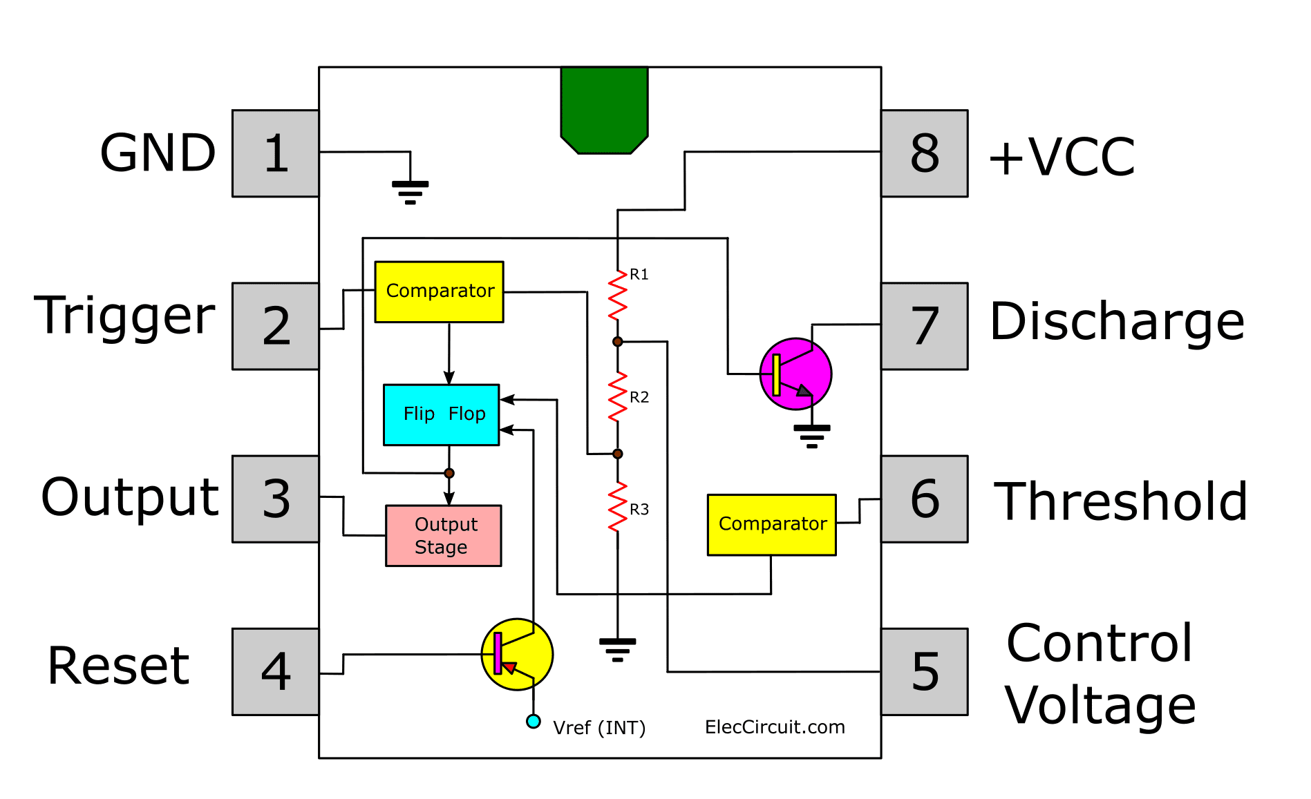
In the time delay mode of operation, the time is precisely controlled by one external resistor and capacitor. If you want to know all the pinout of the 555 timer, what each pin is and what each pin does, see 555 timer pinout. Simple ne555 ic tester circuit diagram. Ic 555 timer ic is one of the most popular integrated circuit chip used for a variety of applications such as astable, monostable, bistable multivibrators, timer circuits, oscillators, pwm (pulse width modulation), ppm (pulse position modulation), square wave generator or pulse generator, etc. Jul 24, 2019 · the working principle of the 555 timer is by considering the block diagram of the 555 timer ic. In this circuit, we will connect the 555 timer to be in astable mode. 555 timer helpers schematic adding of a resistor and capacitor to the trigger will not work for very short trigger or output pulses because there is a rc delay in the decay and recovery of the voltage at the trigger. This circuit is also called a delay. The first comparator has threshold input to pin 6 and control inputs for pin 5. In other words, 555 timer is a circuit which may be connected as a stable or monostable multivibrator. In more simple words, 555 timer is a monolithic timing circuit, which can produce accurate timing pulses with 50% or 100% duty cycle. For a stable operation as an oscillator , the Learn by doing is the best.


0 Komentar